VA-4 Model II Sega Genesis
During the Christmas of 1997 my grandparents bought me a model II Sega Genesis. Unlike my father's NES, this console was actually mine, and as long as I knew that it wasn't just a toy--and could electrocute me--I was free to mess about with it however I wanted. For the entire portion of my youth that I used the system afresh, I never used it, even thought about it in such a way that was out of accordance with the manual.
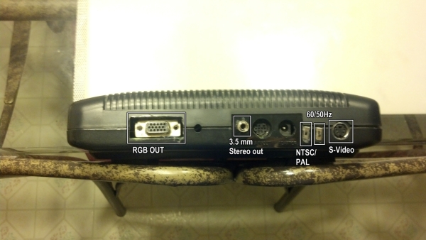
Jumping ahead to my first term at RIT, I had my Genesis and many, many games shipped to my dorm. A floormate and decent friend took note and rather forcfully suggested that we modify the console as to bypass the composite video encoder and output pure RGB video, greatly improving video quality. And so he did, tearing apart the precious gift that was so special to me over the years, soldered to it, and re-assembled it with a new hole in the back and a new port. This was the first of many additions to the console.
The next modification to it was to add a 3.5mm stereo audio jack so that we wouldn't need to use the original video cables for sound. So I took a female connector and soldered it to the breakout of the AV port. Simple stuff.
A few months later the same floormate and I found a very large and very good CRT Television abandoned in a garbage pile. The LHF/UHF tuner was broken(or something), but it still displayed data just fine. So while my friend was busy modifying it to recieve pure RGB input, I soldered a female S-Video port to the same AV breakout (The Sega proprietary AV port has a lot of pins for a lot of things) and we were off to the races yet again.
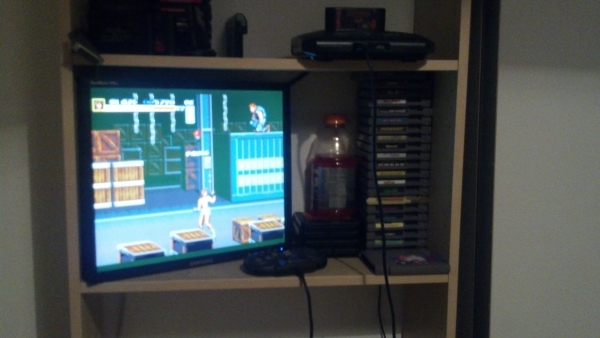
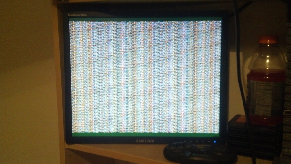
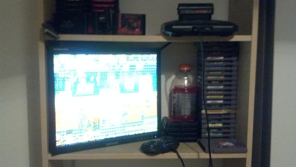
By far the most interesting addition, however, was the bank of switches on the side. After soldering switches to the 50/60Hz and PAL/NTSC jumpers, I looked about an inch to the left and noticed that there were several more jumpers. And even more above. I put the console back together to test the first two switches, then I took it partially back apart to mess with those jumpers. I haven't the slightest idea Sega would have left these on the board. One prevents the VDP from writing out to the encoder, leaving either just the border color or stripes of two palette entries, and another occasionally crashes the console(likely my fault). But two others seem to work together to prevent IO operations to VRAM. This means that one can:
- load a game
- Engage the jumpers
- Swap out the cartridge
- [Rapidly] reset the console
- Start the other game
- Disengage the jumpers
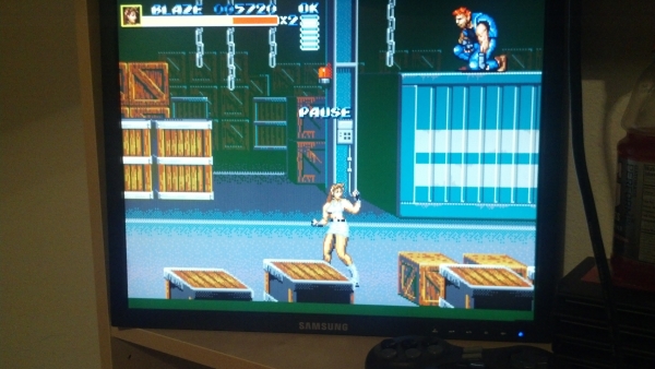
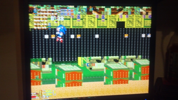
- Play the current game with whatever was left in VRAM by the other game, and hasn't yet been replaced.
Photos
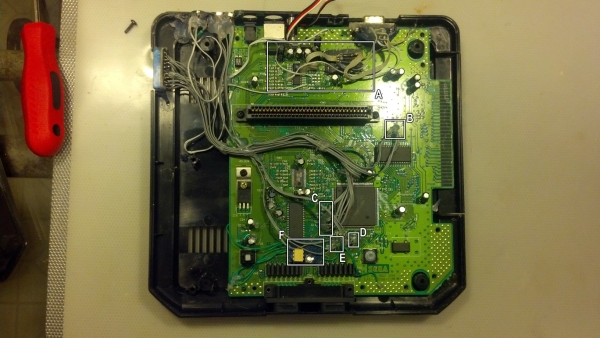
Taking the top off the Genesis we see some of the handywork done inside. In box A we see the working of my friend's RGB modification: sapping from behind the composite encoder, being resisted for correct brightness, and going out to the VGA port.
In box B we see some of the jumpers that are accessed. These connect to switches 3 and 4. They aren't special.
Hiding in box C we find the majority of the jumpers. Towards the bottom of this mess are the two that affect VRAM IO, and above are the other ones that affect video. These are switches 5 through 10.
In the next two boxes is the connection to the jumper that controls refresh rate and the region respectively.
Finally in box E we see the removal of the original evil red LED and its replacement: a very, very bright green LED. The original 1.5 volts or so that the original LED took didn't power the new LED, so now it sits on a chunk of perf board and is powered directly from the little votage regulator on the left of the motherboard, and a opto-isolator connected to the original LED location switches the LED when necessary. The assembly is too tall to fit under the original LED diffuser, so one made of hot glue (almost identical in translucency!) does the job instead.
If it isn't strong enough to use as a frisbee, it's not good enough. That's why everything is reinforced with copious amounts of hot glue.

